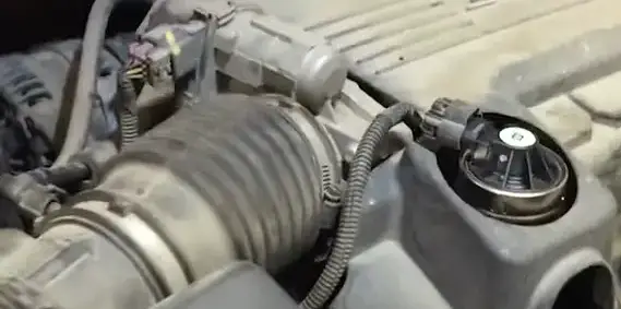
Today, we will provide you with detailed information about the C0561-71 Code and tell you how you can eliminate this problem.
Chevy Dashboard Warning LightsDefinition of C0561-71 Code
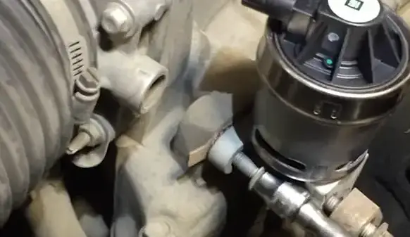
The C0561-71 code is a diagnostic trouble code (DTC) related to a vehicle’s electronic brake control module (EBCM). When triggered, this code typically indicates a problem with the traction control system. The EBCM is responsible for monitoring and controlling the vehicle’s traction, and when the C0561-71 code is present, it can affect the vehicle’s ability to maintain traction in various driving conditions.
This can lead to decreased stability and potential safety concerns for drivers and passengers. This article will explore the definition of the C0561-71 code, its possible causes and symptoms, and potential solutions for addressing the issue. Understanding the implications of this code can help drivers and mechanics accurately diagnose and resolve traction control system malfunctions.
Symptoms of a C0561-71 Error Code
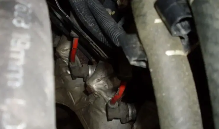
The common symptoms of a C0561-71 error code include the illumination of the check engine light and the ABS light on the dashboard. This error code typically indicates a problem with the powertrain control module (PCM) and may lead to potential powertrain issues. Additionally, the PCM may store freeze frame data that provides information about the conditions present when the error code was triggered.
To verify if it’s a minor issue before addressing potential major problems, it is advisable to first check for simple and common causes such as loose electrical connections, low battery voltage, or faulty wheel speed sensors. These minor issues can sometimes trigger the error code and can be easily resolved.
Suppose the symptoms persist after checking for minor issues. In that case, it is advisable to consult a professional mechanic or a certified technician to diagnose potential major problems such as faulty PCM, malfunctioning ABS module, or other complex powertrain issues. Ignoring a C0561-71 error code and continuing to drive the vehicle with the symptoms present can lead to further damage and should be addressed promptly.
Causes of a DTC C0561-71 Error Code
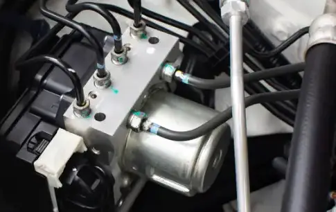
The potential causes of a C0561-71 error code can stem from various issues within the powertrain, EBCM (Electronic Brake Control Module), BCM (Body Control Module), ECM (Engine Control Module), Electronic Stability Control (ESC), IPC (Instrument Panel Cluster), and TCM (Transmission Control Module). These causes may include faulty wheel speed sensors, issues with the ABS, damaged wiring or connectors, malfunctioning electronic components, or communication errors between various control modules. It is important to examine the freeze frame and failure records in the PCM and clear any other associated codes before addressing the C0561-71 error.
It is advisable to contact a local dealership for expert assistance in diagnosing the exact cause of the C0561-71 error code. Professional technicians at the dealership can utilize specialized diagnostic equipment and expertise to pinpoint the root issue, ensuring an accurate and efficient repair process.
In conclusion, the C0561-71 error code can be attributed to various potential causes within the powertrain and control modules, and thorough examination and expert assistance may be necessary for a precise diagnosis and resolution.
Vehicle Stability Enhancement System
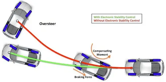
Vehicle Stability Enhancement Systems (VSES) are advanced safety technologies designed to help drivers maintain control of their vehicles in challenging driving conditions. These systems use various sensors and algorithms to monitor the vehicle’s stability and intervene to prevent skidding, loss of control, or rollovers. By continuously adjusting braking and engine power, VSES can help drivers avoid accidents and navigate more confidently through slippery roads, sharp turns, and sudden maneuvers. This technology has become a standard feature in many modern vehicles, providing safety and reassurance for drivers and passengers alike. This section will explore the key components and functions of Vehicle Stability Enhancement Systems and discuss their role in improving road safety and driving experience.
Electronic Brake Control Module
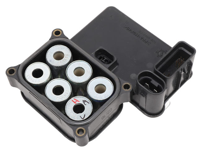
Diagnosing and addressing issues with the Electronic Brake Control Module (EBCM) involves several key steps.
- The first step is to check for any illuminated traction control lights on the dashboard, which can indicate a problem with the EBCM.
- Next, examining each wheel’s sensors is important to ensure they function properly. These sensors are crucial in providing data to the EBCM about wheel speed and traction control.
- Also, reviewing the modules that send signals to the EBCM is essential. These modules include the ABS module, vehicle speed sensor, and wheel speed sensor, among others. Any issues with these modules can affect the EBCM’s performance.
- Once these diagnostic steps have been completed, the next step is to address any issues that have been identified. This may involve repairing or replacing faulty sensors, modules, or the EBCM.
By following these steps, technicians can effectively diagnose and address issues with the EBCM and ensure the proper functioning of the vehicle’s electronic brake control system.
Traction Control Light

To diagnose and address the Traction Control Light on your CUV, you must start by checking the ABS and traction control systems for trouble codes. Use a diagnostic tool to scan for any trouble codes related to the ABS and traction control. Look specifically for GM trouble code C0561, associated with ABS and traction control issues. Additionally, look for indications of a chassis error.
Next, use the ABS to gather data for the traction control system. This will help you identify if there are any faulty parts or components that are causing the Traction Control Light to come on. By gathering data from the ABS, you can pinpoint the specific area of the traction control system that may be malfunctioning.
Once you have identified any trouble codes and gathered data from the ABS, you can use the diagnostic tool to pinpoint the faulty part causing the Traction Control Light to illuminate. Address the issue by replacing or repairing the defective part as needed.
These steps will help you diagnose and address the Traction Control Light on your car, ensuring that your ABS and traction control systems function properly.
Antilock Brake System (ABS)
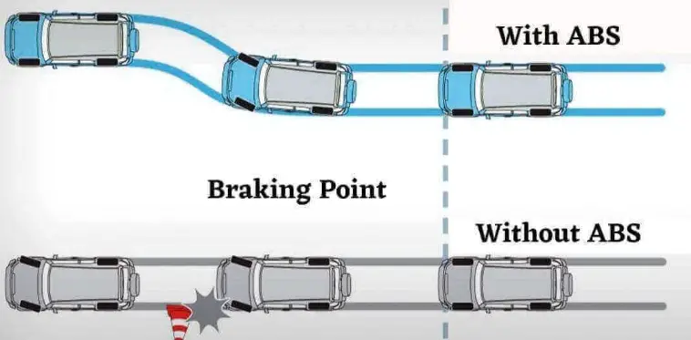
The Antilock Brake System (ABS) prevents the wheels from locking up during braking, allowing the driver to maintain steering wheel control. When the system detects a wheel about to lock up, it reduces the brake pressure, keeping it rotating and maximizing traction. This is achieved through sensors that monitor wheel speed and a control module that regulates brake pressure.
Common issues related to the ABS Fuses include a malfunctioning sensor, damaged wiring, or a faulty control module. Troubleshooting involves checking the sensors for dirt or damage, inspecting the wiring for any breaks or corrosion, and testing the control module for functionality.
The sensors used in the ABS are typically wheel speed sensors, which monitor the rotation of each wheel. The control module processes the data from these sensors and activates the ABS when necessary. Warning signals for ABS issues may include a dashboard warning light, pulsating brake pedal, or unusual noises during braking.
In conclusion, the ABS is a safety feature that prevents wheel lock-up during braking, allowing for better control. Troubleshooting common issues involves checking the sensors, modules, and warning signals for malfunction.
Serial Data Messages
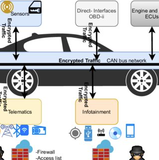
The designated message format outlined in the Background Information should be followed to format and send serial data messages. Each message should include elements such as the message identifier, data bytes, and error-checking information to ensure data integrity. The message format specifies the order and structure of these elements within the message.
To properly structure and transmit the information, start by identifying the message type and assigning a unique identifier to each message type. Then, organize the data elements in the specified order and format for transmission. Once the message is formatted, it can be sent serially using appropriate communication protocols and hardware interfaces.
When transmitting serial data messages, ensure that the message format is consistent and that the recipient device is expecting and able to interpret the incoming data. This will help avoid errors and ensure the transmitted information is correctly interpreted and utilized.
Adhering to the designated message format and properly structuring the necessary data elements can effectively transmit and receive serial data messages.
Check Engine Light and Engine Light Scan Tool
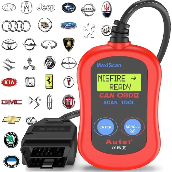
To use an engine light scan tool to check for trouble codes and address a service traction control issue, start by locating the vehicle’s onboard diagnostics (OBD) port, typically found underneath the dashboard. Connect the scan tool to the OBD port, ensuring a secure connection. Follow the manufacturer’s instructions for retrieving trouble codes, which may involve turning the vehicle’s ignition on without starting the engine and navigating the scan tool’s menu.
Once the trouble codes are retrieved, look for any related to the traction control system. The codes may indicate sensor, wiring, or traction control module issues. Address any matters identified by inspecting and repairing the components involved. This may include checking for loose or damaged wiring, replacing faulty sensors, or reprogramming the traction control module.
You can effectively diagnose and resolve service traction control issues using an engine light scan tool to retrieve trouble codes and address any traction control system-related issues. Following the manufacturer’s instructions ensures accurate trouble code retrieval and proper troubleshooting.
ABS Light and Body Control Module (BCM)
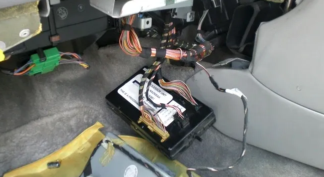
When addressing the ABS light and its connection to the Body Control Module (BCM), it is important to first check for any possible issues or malfunctions with the Electronic Brake Control Module (EBCM). This can be done by looking for dashboard warnings or abnormal braking system behavior that may indicate a problem with the BCM’s control over the ABS.
If the ABS light is illuminated on the dashboard, it could indicate a problem with the EBCM or its connection to the BCM. Sometimes, the ABS light may blink, signaling a fault in the braking system.
To address this issue, it is recommended first to check the brake fluid level and ensure it is correct. Next, inspect the brake system for any leaks or damaged components. If no visible issues are found, it may be necessary to use a diagnostic tool to scan for error codes in the EBCM and BCM.
By following these steps, any potential issues with the ABS light and its connection to the BCM can be identified and addressed, ensuring the proper functioning of the braking system.
Engine Control Module (ECM) and Traction Control Fuse
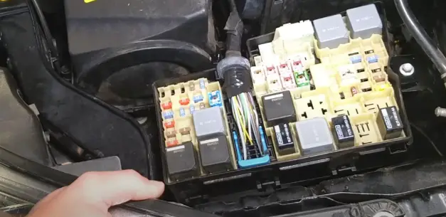
Locate the fuse box in your vehicle to check the Engine Control Module (ECM) and Traction Control fuse. This is usually found under the dashboard or in the engine compartment. Once the fuse box is located, open the cover to access the fuses.
Next, visually inspect the fuses for any signs of damage or burn marks. The ECM and Traction Control fuse should be labeled on the fuse box cover or in the owner’s manual. If you find a damaged or blown fuse, it must be replaced.
To replace the fuse, use a fuse puller or carefully remove the fuse with your fingers. Then, replace it with a new fuse of the same amperage rating. This information can also be found on the fuse box cover or in the owner’s manual.
After replacing the fuse, close the box cover and start the vehicle to check if the issue has been resolved. If the problem persists, it may be necessary to seek professional assistance. But in most cases, this simple task will help ensure that the ECM and Traction Control systems function properly.
Steering Position Sensors and Electronic Braking Systems
To check and reset your car’s steering position sensors and electronic braking systems, ensure the battery is connected properly and check for any broken wires to the wheel speed sensors. Use a Tech 2 scanner to diagnose and clear any error codes related to the ABS.
First, inspect the battery connection to ensure it is secure and producing the proper voltage. Next, visually inspect the wheel speed sensors for any signs of damage or broken wires. If any issues are detected, they must be repaired or replaced before proceeding.
Connect a Tech 2 scanner to the car’s diagnostic port and follow the on-screen instructions to access the ABS. The scanner will be able to read any error codes related to the steering position sensors and electronic braking systems. Clear any codes that are present to reset the system.
By following these steps, you can effectively check and reset your car’s steering position sensors and electronic braking systems, ensuring they are in proper working condition for safe driving.
Diagnosis Procedure for DTC C0561-7 Error Code
When a vehicle’s onboard diagnostic system detects a C0561-7 error code, it indicates a problem with the traction control system. To diagnose this issue, several steps and procedures must be followed to pinpoint the exact cause of the error code. This diagnostic procedure involves using a scan tool to retrieve the trouble codes stored in the vehicle’s computer system.
Additionally, a visual inspection of the wiring, connectors, and components related to the traction control system is necessary to check for any visible damage or loose connections. Further testing of sensors, modules, and the vehicle’s communication network may also be required to identify the underlying issue causing the C0561-7 error code. Automotive technicians can effectively diagnose and address the traction control system problem by following these diagnostic procedures, restoring the vehicle’s optimal performance and safety features.
Reading the Codes with a Code Reader
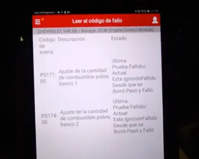
First, to read codes with a code reader, locate the vehicle’s OBD-II port, usually found under the dashboard on the driver’s side. Then, connect the code reader to the port. Next, turn on the vehicle’s ignition without starting the engine. The code reader will power on and may prompt you to select the vehicle’s make and model.
Navigate through the menu options on the code reader to access the codes. Once the codes are displayed, refer to the code reader’s manual for specific instructions on interpreting the codes. The manual will provide details on what each code means and potential issues with the vehicle that corresponds to the codes.
By following the manual’s instructions, you can determine the specific issues with the vehicle and make informed decisions about necessary repairs. Always refer to the manual for accurate interpretation of the codes and troubleshooting advice. This process allows for quick and efficient diagnosis of potential issues with the vehicle.
Analyzing the Error Codes with the Help of Service Manuals/Charts/Graphs/Data Logging
When faced with error codes in a system or equipment, utilizing all available resources to identify and address the underlying issues is crucial. Examining the service manuals, charts, graphs, and data logging to understand the error codes comprehensively. These resources often contain valuable information that can provide insight into the root cause of the errors and guide the troubleshooting process.
Pay close attention to any specific error code explanations or common patterns that may be present in the documentation. This can help establish a diagnostic process and determine appropriate steps to resolve the errors. Additionally, use the data logging to track and analyze the occurrence of the error codes over time, which can reveal trends or patterns that may indicate underlying issues.
Utilizing the information in the service manuals, charts, graphs, and data logging makes it possible to effectively analyze error codes and identify the necessary troubleshooting steps to rectify the issues. Use keywords such as service engine manuals, charts, graphs, data logging, error codes, and troubleshooting in these processes.
Sources:
en.m.wikipedia.org
amzn.to
What is the cause of Code C0561?
Code C0561-7 indicates a problem with the vehicle’s traction control system. To diagnose the issue, scan the trouble codes stored in the vehicle’s computer system and visually inspect wiring and connectors related to the traction control system. Further sensors, modules, and communication network testing may also be required to identify the underlying issue causing this error code.
How do you fix the traction control code C0561-71?
1. Use a scan tool to read the trouble codes stored in the vehicle’s computer system.
2. Visually inspect wiring, connectors, and components related to the traction control system for any visible damage or loose connections.
3. Test sensors, modules, and communication networks for any issues causing the error code C0561-7.
4. Make repairs as necessary to fix the issue with the traction control system.

